Getting started
This page takes you from nothing to your own design running on an FPGA board. You'll install Logix IDE, open an example that blinks an LED, look at what the tools tell you about it, upload it to your board, and then change it and save it as your own project.
The steps use the iCESugar v1.5 board as the example. They're the same for every board Logix IDE supports; only the example's details differ.
What you need
- A Mac with Apple Silicon (M1 or newer) and macOS 11 or newer.
- An FPGA board and the USB cable that connects it to your Mac. You can follow most of this page without a board; only the upload needs one.
- An internet connection the first time you start Logix IDE.
There's nothing else to install: Logix IDE downloads the FPGA tools it needs.
1. Install Logix IDE
Install Logix IDE as Installing describes: download it, allow it to open, and drag it into the Applications folder.
2. Start Logix IDE
Open Finder, click Applications in the sidebar and double-click
Logix IDE (or press Command-Space, type Logix IDE and press Return).
Dragging it into Applications only copied it, so this is its first start. The
first time, it
downloads its FPGA tools, which takes a few minutes. The status bar at the
bottom of the window shows the progress, and the output area above it shows
what's happening:
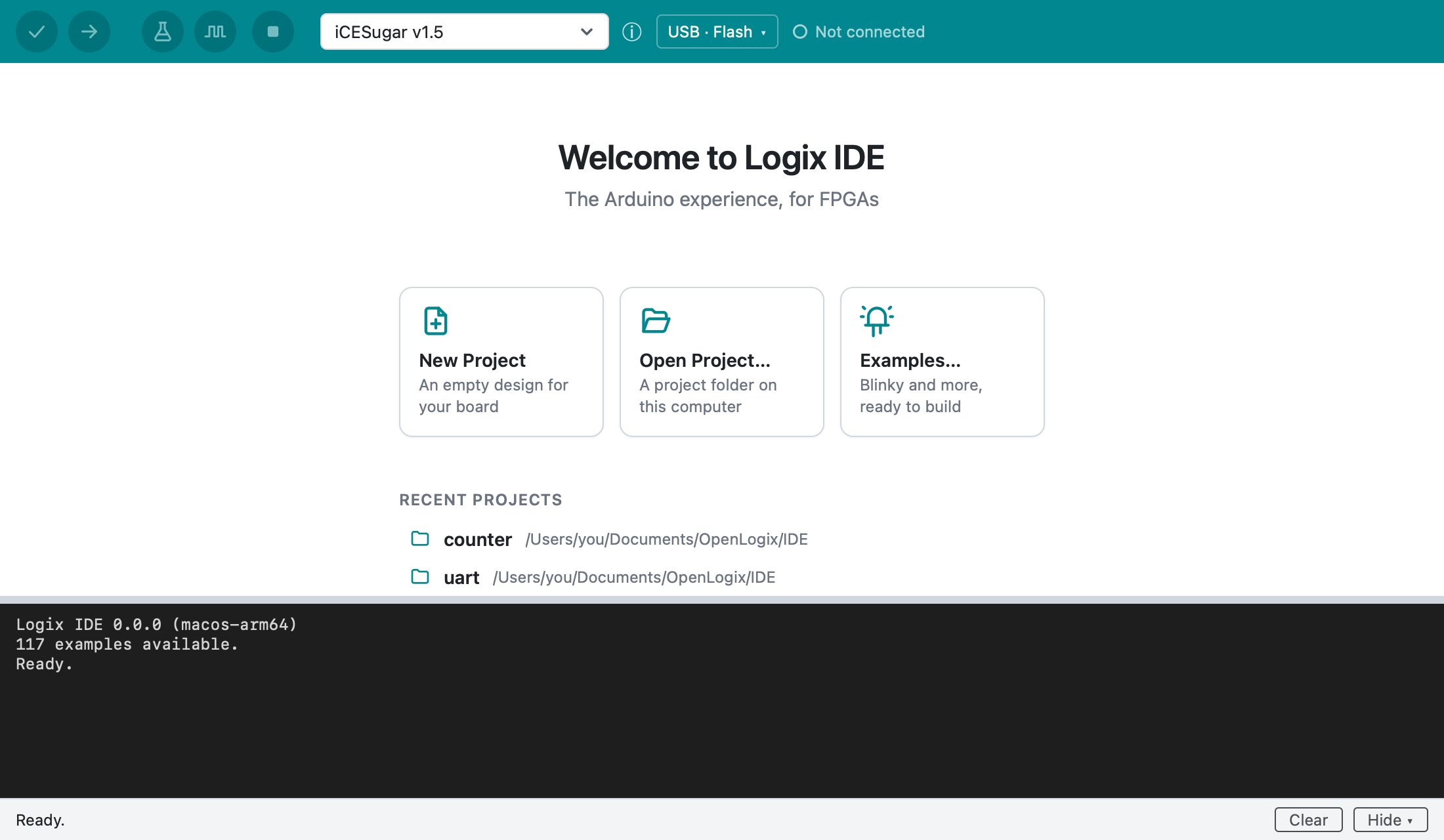
Downloading the examples 2026.11.12...
The examples 2026.11.12 downloaded.
Downloading Logix Engine 2026.11.12...
Logix Engine 2026.11.12 downloaded.
Downloading the FPGA tools. The first time can take a few minutes.
Downloading logix-core 2026.11.11...
FPGA tools downloaded (logix-core).
117 examples available.
Ready.
When the output says Ready., you can start. Later starts take only a few seconds and work without internet. Logix IDE checks for newer releases of Logix Engine, its FPGA tools and the examples once a day, when you use it, and downloads them by itself; Help > Check for Updates checks now.
The window shows the start screen, with buttons for a new project, an existing project and the examples:
3. Connect your board and select it
Connect the board to your Mac with its USB cable. Then select it in the board list in the toolbar: type part of its name to find it. The list starts with the boards you've used recently, followed by every board grouped by FPGA family. The iCESugar v1.5 is selected at first.
Next to the board list, Not connected changes to Connected when Logix IDE finds your board on USB.
4. Open the Blinky example
Click Examples… on the start screen. The window lists the examples for your board: select blinky and click New Project. (On a few boards, the first example is called ledon.)
Blinky opens as a new project. Its files are in tabs above the editor:
main.vis the design, written in Verilog. On the iCESugar v1.5 it blinks the RGB LED in green, about once a second. Its comments explain each part.pinout.pcfis the pin file: it says which FPGA pins connect to what on the board, such as the clock and the LED.main_tb.vis a testbench: it checks the design on your Mac, without a board.
5. Verify the design
Click Verify  ,
the first button in the toolbar. Logix IDE checks the design for common
errors and builds it. The status bar then says how much of the FPGA the
design uses and how fast its clock can run:
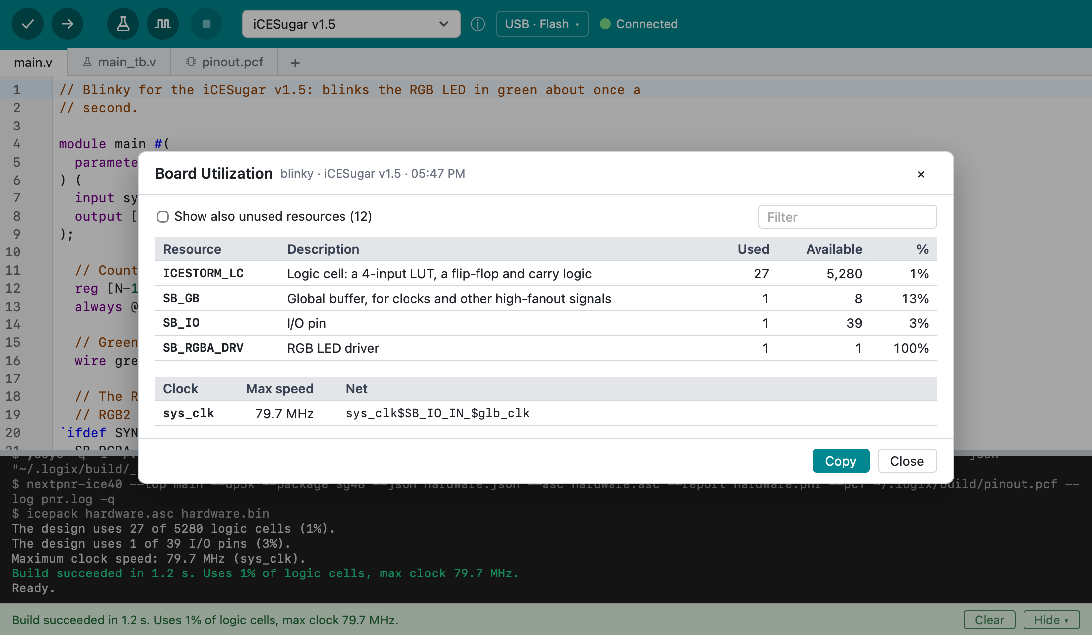
Build succeeded in 1.2 s. Uses 1% of logic cells, max clock 79.7 MHz.
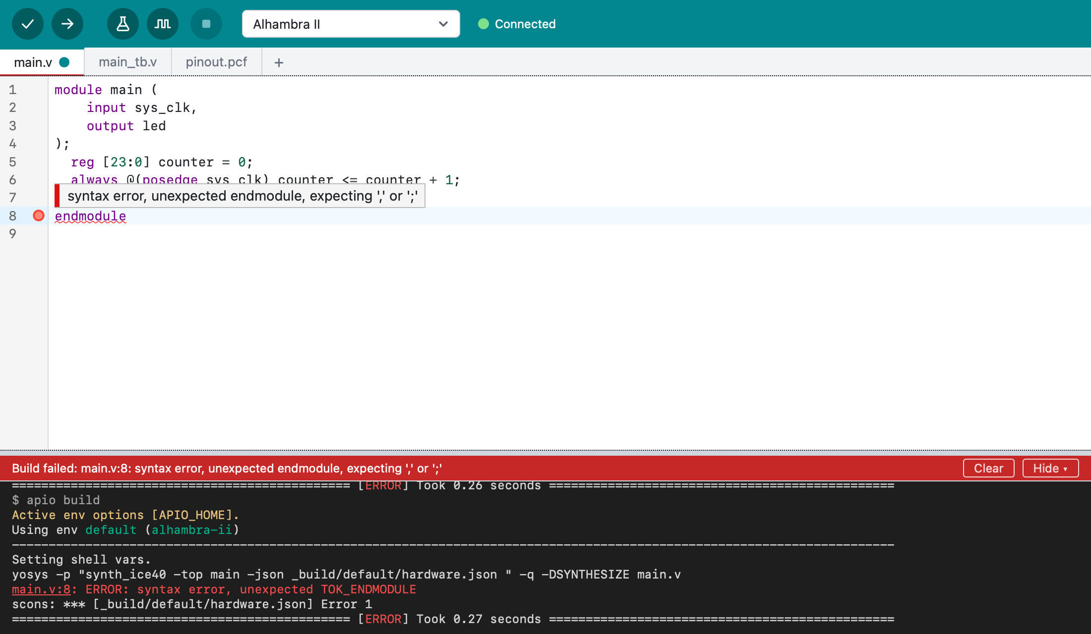
If there's an error, Logix IDE marks its line in the editor and the status bar says what's wrong; hover over the mark to read the message. Syntax errors are marked as you type, before you click Verify:
6. Look at the board utilization
Verify's message gives the totals. For the details, choose Project > Board Utilization…: it lists each FPGA resource the design uses, such as logic cells, RAM blocks and I/O pins, with how many the FPGA has, and the design's clocks with their maximum speeds.
7. See the design as a diagram
Choose Project > Show Diagram. Logix IDE draws the design as a schematic
in a window of its own: the counter's register, the adder that counts, and the
pins. Hover over a block for its details, and double-click it to see its line
in main.v. You can keep the window open while you work: it's drawn again after
each Verify.
8. Run the tests
Click Run Tests  .
Logix IDE runs the testbench,
main_tb.v, which drives the design with a
clock and checks that the LED turns on and off when it should. The output says
whether each test passed. Run the tests after every change, to make sure the
design still works.
9. Simulate the design
Click Simulate  .
Logix IDE runs the testbench too, but instead of a pass or fail result it opens
the design's signals in GTKWave, a waveform viewer. There you can see each
signal change over time, such as the counter and the LED, to understand why
the design behaves as it does.
Testbenches and simulation explains both.
10. Upload it to the board
With the board connected, click Upload
 , next to Verify.
Logix IDE builds the design if it changed and programs the board. A few
seconds later the LED starts blinking: on the iCESugar v1.5, the RGB LED
blinks green.
The design is stored in the board's flash memory, so it runs again whenever the board gets power, even without your Mac.
11. Modify the design
Now make it yours. In main.v, the counter's width N sets how fast the LED
blinks: each step down doubles the speed. Find this line:
parameter N = 24 // Counter width: 2^24 cycles at 12 MHz is about 1.4 s.
Change 24 to 22 and click Upload. The LED now blinks four times as
fast.
12. Save it as your project
Choose File > Save Project and give the project a name. Logix IDE creates
a folder for it, in ~/Documents/OpenLogix/IDE by default, and lists it under
Recent projects on the start screen.
13. Explore the boards
Open the board list in the toolbar to see every board Logix IDE supports, 81 so far. The ⓘ button next to the list opens the Board Explorer, with the selected board's facts: its FPGA, what its pins connect to (the clock, LEDs, buttons), how it's programmed, and its examples.
14. Explore the settings
Choose Logix IDE > Settings… to change how Logix IDE works:
- Projects folder location: where new projects are saved.
- Editor font size, Interface scale and Theme (System, Light or Dark).
- Show the output: when the output area comes back by itself after you hide it.
- Show lint warnings on Verify: turn it off to skip the design check.
- Check code while typing: mark syntax errors as you type.
If something goes wrong
| Problem | What to do |
|---|---|
| macOS says Logix IDE can't be opened | Run the xattr -c command from Installing again, then install it again. |
| The FPGA tools don't download | A red bar shows the problem. Check your internet connection and click Retry. |
| Upload can't find the board | Check that Connected shows next to the board list, and try another USB cable: some cables only charge. |
| Your board isn't in the list | It isn't supported yet. To ask for it, choose Help > Report a Problem. |
Troubleshooting covers these and more.
Next steps
- Take the tour of the window: the toolbar, the files of a project and what each part does.
- Open more examples with File > Examples…, such as rgb-led on the iCESugar v1.5.
- Look up menus, keyboard shortcuts and settings in Using Logix IDE.